Wiring diagram
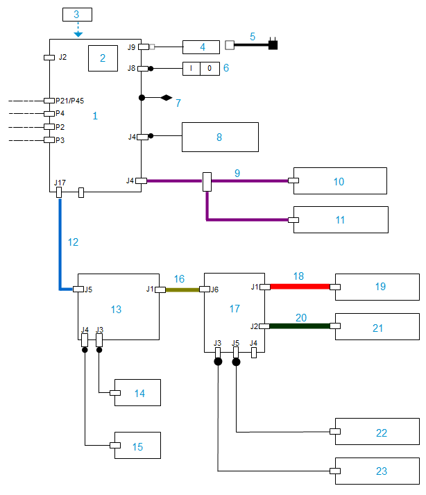
No. | Reference | Description | Qty | Info |
|---|---|---|---|---|
| 1 | L11R92 | Fitted motherboard (PXA270) | 1 | |
| 2 | L11MS4 | Programmed SD card (PXA270) | 1 | |
| 3 | L11MS2 | External update USB key | 1 | |
| 4 | CA4062 | 12V external power supply | 1 | |
| 5 | CA6320 | Europe power cable | 1 | |
| 5 | N66R43 | Power cord US | 1 | |
| 6 | L1107H | Cabled switch | 1 | |
| 7 | L1205F | LCD Display | 1 | |
| 8 | L11S78 | Screen subset | 1 | |
| 9 | L11T01 | Jaw motor extension | 1 | |
| 10 | L11S41 | Front jaw clamps | 1 | |
| 11 | L11S40 | Rear jaw clamps | 1 | |
| 12 | L11N04 | Extension | 1 | |
| 13 | L11R05 | Map transfer framework equipped | 1 | |
| 14 | L11S51 | Transfer engine with plate | 1 | |
| 15 | CE2090 | Wired transfer cell | 1 | |
| 16 | L11n03 | Transfer card layer | 1 | |
| 17 | L11R04 | Transfer card equipped | 1 | |
| 18 | L11N02 | Z Card layer | 1 | |
| 19 | L1111Z | Z card equipped | 1 | |
| 20 | L11N01 | Rhô card layer | 1 | |
| 21 | L1111Y | Rho card equipped (for PXA) | 1 | |
| 22 | L1110N | Theta equipped motor | 1 | |
| 23 | CE2091 | Wired cell | 1 |
A: Screen
B: Optical block
C: USB
D: Tracing table
Camera cable L14R75 is discontinued and replaced by cable B11R05.
For more information refer to information notes:
no.1076 (New motherboard_ New camera_New USB subset),
no.1193 (Standardisation of camera cable B11R05).